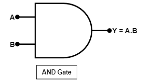
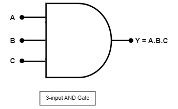
An AND gate is a fundamental logic gate in digital electronics. AND gate has two or more inputs and a single output. AND gate works on logical multiplication. The output will only be High if all the inputs are high, and even if one input is Low, the output will be low. As stated earlier, AND gate can have multiple inputs though 2 and 3 inputs AND gate are the most common.
2-input AND Gate:
2-input AND gate is the simplest form of AND gate. As the name suggests, it has two inputs and one output.

Boolean expression: Y = A.B (where A & B is input and Y is output)
Truth Table:
| Input | Output | |
| A | B | Y |
| 0 | 0 | 0 |
| 0 | 1 | 0 |
| 1 | 0 | 0 |
| 1 | 1 | 1 |
3-Input AND Gate:
Instead of 2 inputs, if there are inputs, it is called 3-input AND Gate.

Boolean expression: Y = A.B.C (where A, B, C are input and Y is output)
Truth Table:
| Input | Output | ||
| A | B | C | Y |
| 0 | 0 | 0 | 0 |
| 0 | 0 | 1 | 0 |
| 0 | 1 | 0 | 0 |
| 0 | 1 | 1 | 0 |
| 1 | 0 | 0 | 0 |
| 1 | 0 | 1 | 0 |
| 1 | 1 | 0 | 0 |
| 1 | 1 | 1 | 1 |
Realization of AND Gate using simple circuit:
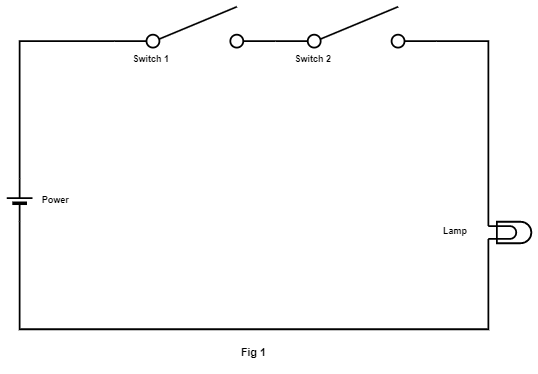
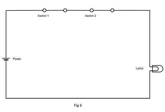
We can demonstrate the working of the AND using a simple circuit consisting of a battery, two switches in parallel, and a bulb. The battery’s positive terminal is connected to the bulb through the two switches, which are in series, while the negative terminal is connected directly to the bulb. Now let’s consider Switch 1 as input A, Switch 2 as input B, and the bulb as output Y. When both Switch 1 and Switch 2 are closed (turned ON), the circuit will be complete, and the bulb will light up (fig-2). If either Switch 1 or Switch 2 (or both) is open (turned OFF), the circuit will be broken, and the bulb will not light up (fig-1).


